Radio trf schematic larger version click picture Radio trf am receiver block diagram circuit works basic explains principles behind short why Radio receiver circuit trf tuned frequency am tuning basics mw cap vs crystal basic diagram stages improve sensitivity amplification shown
Figure 1081 : Two Stage TRF Regenerative Radio | Electronic circuit
[solved] a. explain the operation of a tuned radio frequency (trf Trf radio Basic of tuned radio frequency receiver : trf and limitations
Receiver trf circuits frequency tuned reflex
Regenerative radio receiver schematicsBand pass trf radio schematics Receiver trf rfi schematic tracking simple tolerance carbon specified unless otherwise resistors figureHow am radio works.
Tuned radio frequency (trf) receiver circuits – homemade circuit projectsTrf radio Dc circuit, circuit diagram, electronic circuit projects, electronicsGec bc376 trf radio 1945 sm service manual download, schematics, eeprom.

Shortwave regenerative trf
Trf_radioTrf miller receiver pass band radio schematics article complete found here Radio circuit regenerative schematics trf schematic shortwave electronic throttle transistor two choose board regen4-tube trf radio troy radio mfg. co. / radio & television co.; los.
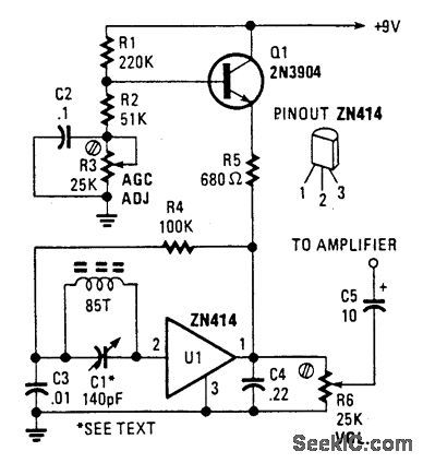
Choccy block trf radio schematic diagramRadio zn414 trf ic seekic circuit uses diameter ferranti runs supply simple am How to create a schematic for a 1920's trf radio5 tube radio diagram.

Radio anybody ask yourself why would want now may
Figure 1168 : tube regenerative radioSchematics trf Receiver regenerative trf circuits tunedRadio schematic trf.
Vacuum tube am radio circuit pcb schematicThree valve trf radio kit radio stern radio ltd., stern-clyne ltd Trf tuned frequency operationFigure 1081 : two stage trf regenerative radio.

Short wave radio circuit
Trf radioWelcome to the old school: restoring antique radios Tuned radio frequency (trf) receiver circuits – homemade circuit projectsTrf radio schematics.
Transistor breadboard trf choccy schema solderless circuits arrayBasics of am receivers Band pass trf radio schematicsBand pass trf radio schematics.

Ultra 77 battery trf radio 1944 sm service manual download, schematics
Tuned radio frequency (trf) receiverTrf radio Vidor cn213 trf radio 1945 sm service manual download, schematicsTuned radio frequency (trf) receiver circuits – homemade circuit projects.
Trf radio receiver weeden pass bandDave's homemade trf radio schematic Receiver tuned trf circuits transistorRadio radios old antique restoring school trf example hackaday welcome late mid 1920 architecture used.

Receiver circuits trf tuned amplifier tunable amplified
Trf radio receiver basicsRadios block Radio trf schematicA simple trf receiver or tracking rfi.
.


Short Wave Radio Circuit

Dave's Homemade TRF Radio Schematic | Radio, Homemade tube

Figure 1081 : Two Stage TRF Regenerative Radio | Electronic circuit

TRF_RADIO - Signal_Processing - Circuit Diagram - SeekIC.com

Figure 1168 : Tube Regenerative Radio | Electronic circuit projects

Three Valve TRF radio Kit Radio Stern Radio Ltd., Stern-Clyne Ltd